Featured Document
-
-
The first steps of this guide will be about installation and configuration of the Slic3r PE software. If you already have a copy of the software available, skip to step number 3.
-
The recommended software used for file preparation and processing when printing with the Prusa MK3/MK3S printers is called Prusa Slic3r. Use the link to download the installation package onto your own computer if desired.
-
The computer in the IDC main assembly area has a copy of Prusa Slic3r already installed as well.
-
Download and open the installer. Follow the instructions to complete the installation.
-
-
-
The first critical step to Slic3r PE's proper function is configuring it for the correct printers.
-
Open Slic3r PE and select Configuration > Configuration Assistant.
-
Select Next until you reach the page displaying the 3D printers.
-
From the list of printers, select the 0.4 mm and 0.6 mm nozzle options for the Prusa MK3 and MK3S printers. These are the types of printers and nozzles used in the IDC assembly area.
-
Select Finish in the Configuration Assistant to complete the configuration.
-
-
-
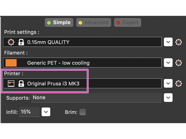
Once configured, you must select which machine, material and layer resolution you wish to use, as well as settings for infill and supports.
-
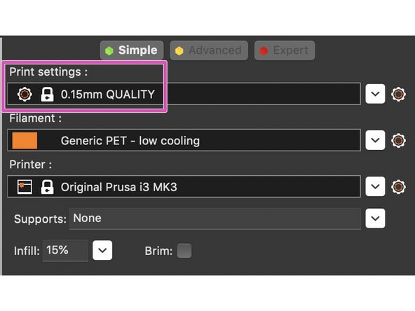
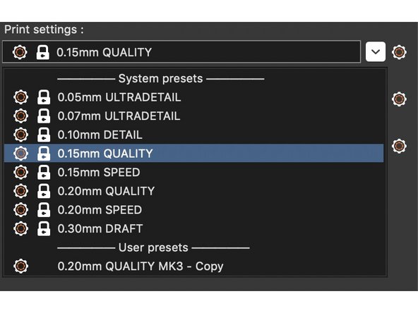
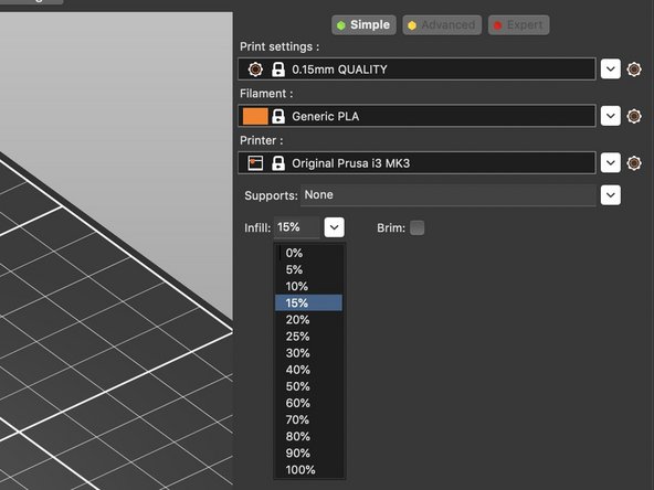
Expand the dropdown menu for Print Settings (layer height) and select a desired resolution.
-
You will see the words QUALITY, SPEED, DRAFT, etc. next to each layer height in the menu. These selections generally affect the speed of the print, but printing faster can often have a greater risk of a failed print. Using the QUALITY setting is usually recommended.
-
-
-
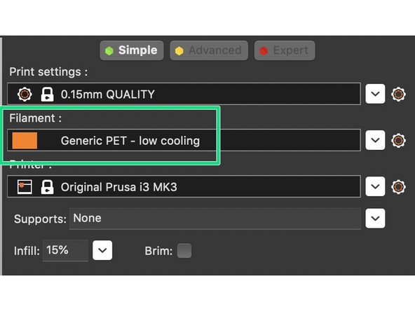
From the Filament dropdown menu, select the filament you will be using. typically the 'generic' settings work fine.
-
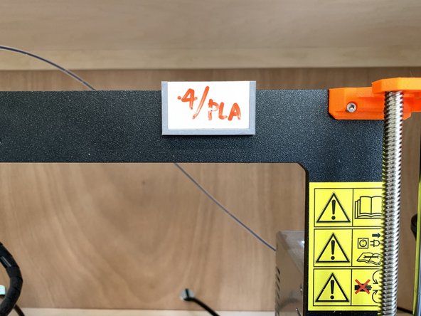
Make sure to choose the appropriate filament profile in Slic3r, either whatever is already loaded into the printer or what you plan to load. There are placards on each printer displaying what material and nozzle size are currently loaded.
-
The most frequently used filament is PLA (Polylactic Acid). It is good general purpose, high printability and low toxicity filament for rigid parts. It is most commonly loaded in the IDC's Prusa printers.
-
There are small placards on each printer in the main assembly area wooden cabinet which display the type of filament and nozzle size currently loaded in the printer.
-
-
-
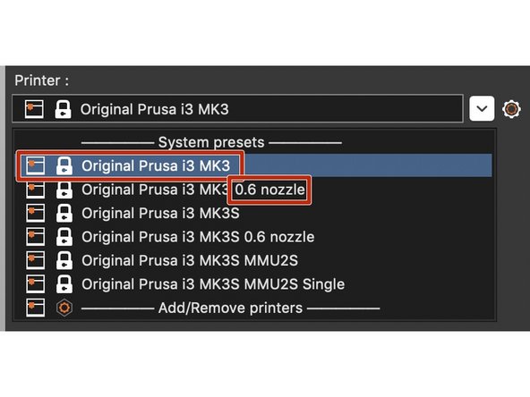
You will select a printer profile based on two factors: the model of printer and nozzle size. Both are very important to select correctly. Each model of printer will be displayed with whatever nozzle size options you selected in the configuration assistant.
-
Open the Printer dropdown menu and select the appropriate printer. Printers listed without a nozzle size after the name use the stock 0.4 mm nozzle size. All printers in the shop using anything other than a 0.4 mm nozzle are clearly labeled with the nozzle currently installed.
-
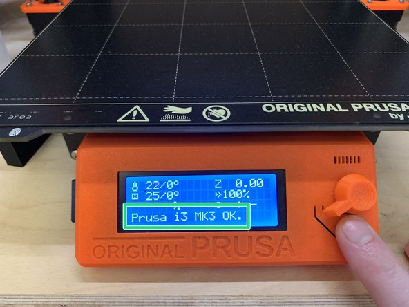
If you are unsure of which model printer you will be using for printing, you can find out by pressing the reset button (located below the dial) on the display face, and then read the model name at the bottom of the LCD display.
-
-
-
Generally .STL is the file format used for 3D printing. Slic3r will also accept .OBJ format files.
-
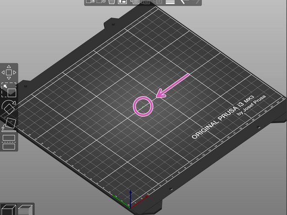
Go to File > Import > Import .STL/.OBJ/.AMF/.3MF, and select your file from wherever you have saved it.
-
Slic3r operates in mm units, so if you designed in inches or cm, your model will import small, or extremely small in scale.
-
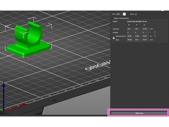
If your model imports at the wrong size, scale your part by a factor of 1000 (for cm) or 2540 (for inches) using the scale entry field at the right side of the screen.
-
You only need to enter a value in one of the axis fields to scale the model proportionately. You can check the final size after scaling by referring to the Size entry fields underneath Scale factors.
-
-
-
Model orientation is an important factor in achieving a successful 3D print. This video from Maker's Muse is a good guide to start with for part orientation best practices.
-
Part orientation can be done three ways in Slic3r. This is method one:
-
Enter a numerical value in one or more axis entry fields of the Rotate section of the Object manipulation menu.
-
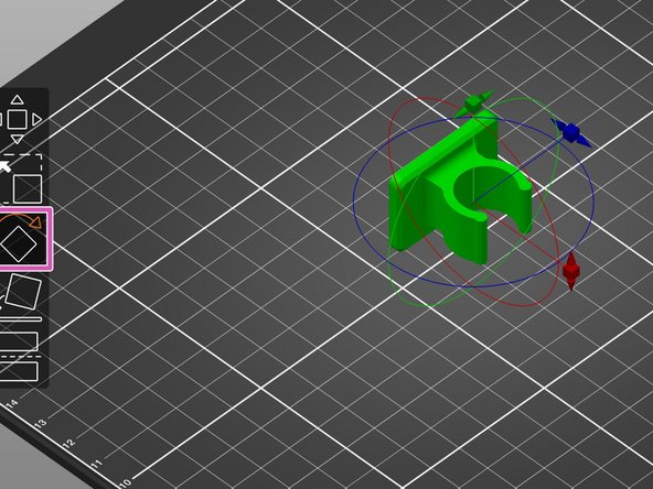
Manually rotate using the Rotate tool in the toolbar at left of the screen. Once selected, the model is rotated manually by clicking and dragging one of the square sliders to the desired position.
-
It is easy to miss the mark with this tool and accidentally leave your part at a slight angle even though it looks flat, which will result in a failed print due to not having sufficient contact with the print bed.
-
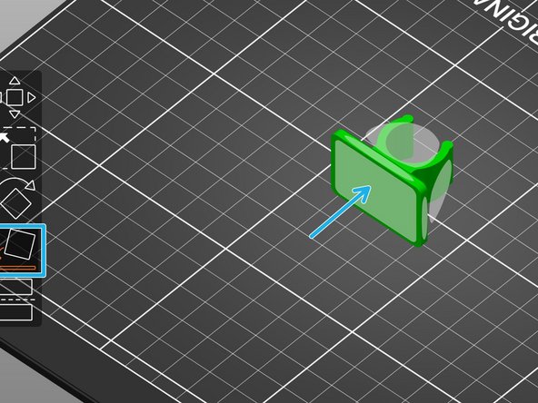
Use the place on face tool in the toolbar at left of the screen. A selectable face will be superimposed on each available flat face, and can be snapped to the print bed by selecting it. This is the recommended tool to use when possible for ease and effectiveness.
-
-
-
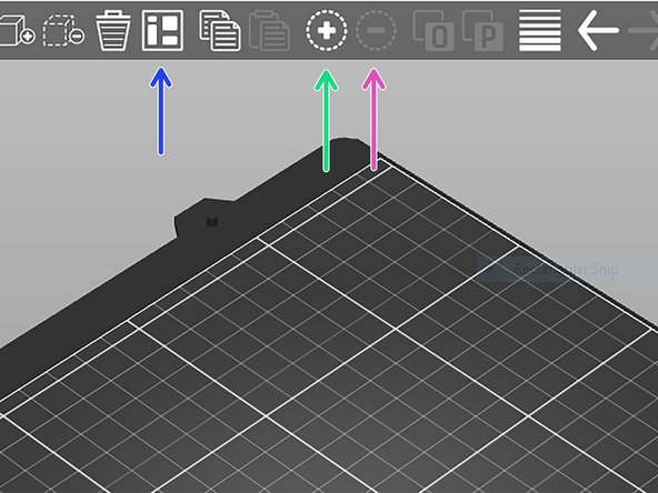
If you wish to duplicate your model to print multiple instances, select (click on) it, and then select the duplicate (+) icon from the top toolbar. Or use the keyboard shortcut Shift +.
-
Items can be subtracted by simply selecting and using the delete key, or using the minus (-) icon in the top toolbar. Or, you can use the keyboard shortcut Shift - to reduce the number of instances.
-
To move your duplicated model, you can select and drag individually, or select the Auto arrange icon from the top toolbar, and Slic3r will automatically place your models on the build plate.
-
-
-
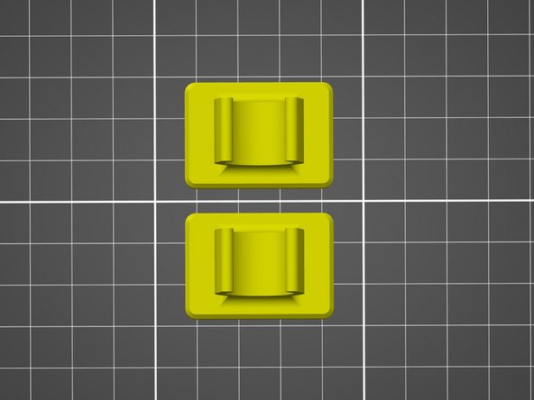
The infill value determines the sparsity of the interior structure of your part, which saves material, as opposed to printing the part completely solid. Higher density of the interior structure can increase the part's strength, while lower density reduces the printing time and part weight.
-
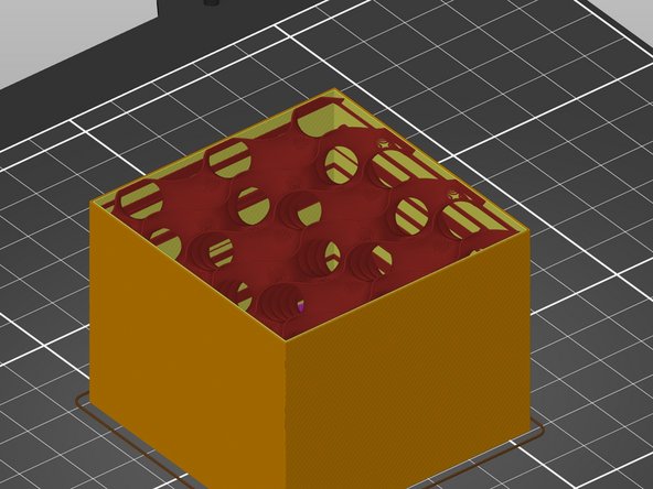
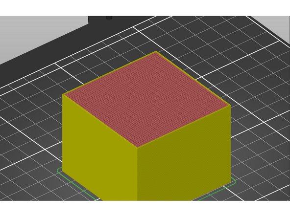
Expand the Infill dropdown menu on the right side of the screen, and select a percent value. The two examples pictured in this guide are 5% (more sparse) and 70% (more dense). For scale, the cube pictured is just under two inches square.
-
-
-
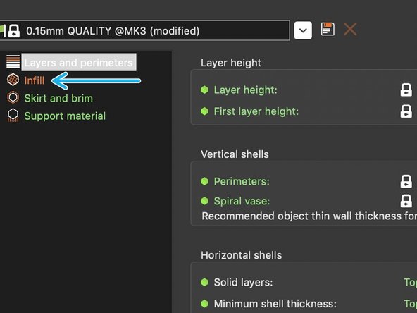
Not only the density, but also structure of the infill play a role in the time needed for printing, but also how the part will react under different types of force applied.
-
Select the Print settings option at the top of screen, above the top toolbar.
-
In the upper left corner of the window, select Infill.
-
Expand the Fill pattern dropdown menu and select a pattern of infill structure.
-
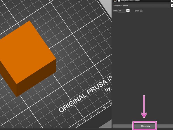
Select Plater from the top of the screen, in the same bar you found the Print settings option.
-
At the bottom right corner of the screen, select the Slice now button.
-
-
-
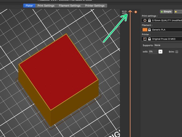
Once you have sliced your model, you can preview the simulated print.
-
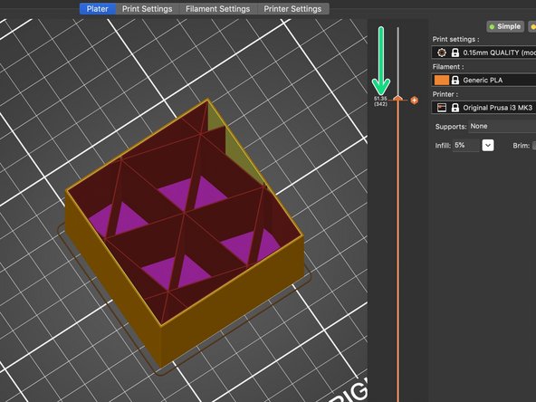
Select and drag the slider handle which appeared after slicing your model, this will allow you to see the internal structure of your part.
-
The 15% default value and structure Slic3r uses are typically sufficient for infill, but in some cases it can be helpful to experiment with different densities and structures depending on your time and application limitations and factors.
-
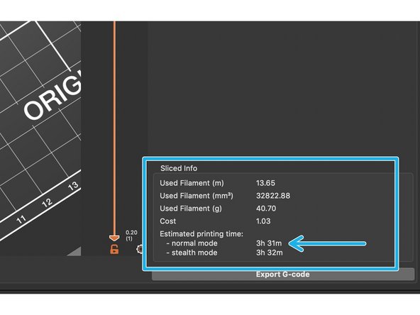
Once you have sliced your model, there will be an information window at the bottom right of the screen displaying an estimated print time. You can often reduce the print time by decreasing the infill percentage.
-
-
-
Slic3r generates support structures (when selected) based on what it determines necessary in the part's geometry, meaning overhangs and other features which would otherwise print in unsupported space. Supports can determine the success or failure of a print. This article describes when and how to use supports in 3D printing.
-
The simplest way to generate supports is by selecting the Supports dropdown menu, and then selecting Everywhere. This will apply supports wherever the software has sensed they might be needed.
-
After selecting your support command, select Slice now at the bottom right of the screen to generate the supports and print simulation based on all of the selections you have made so far in Slic3r.
-
-
-
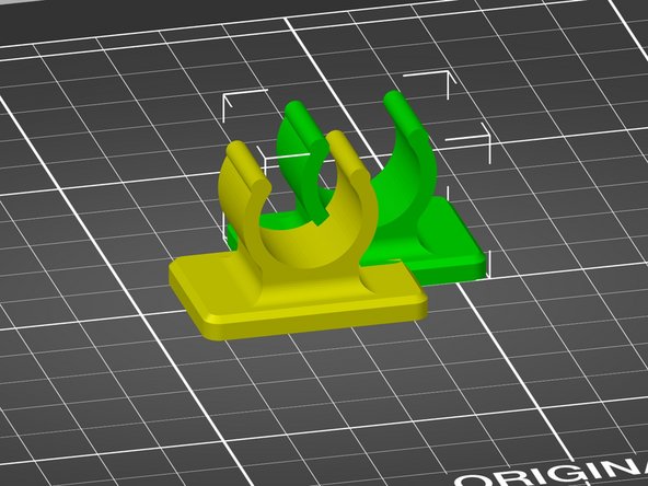
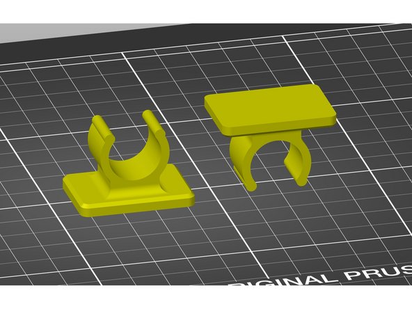
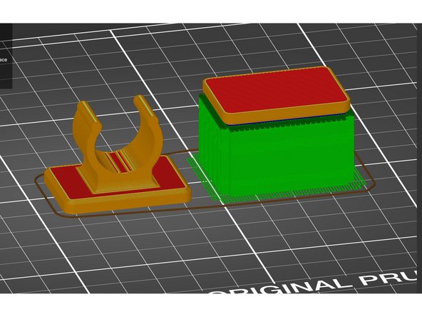
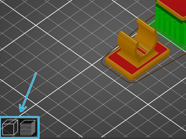
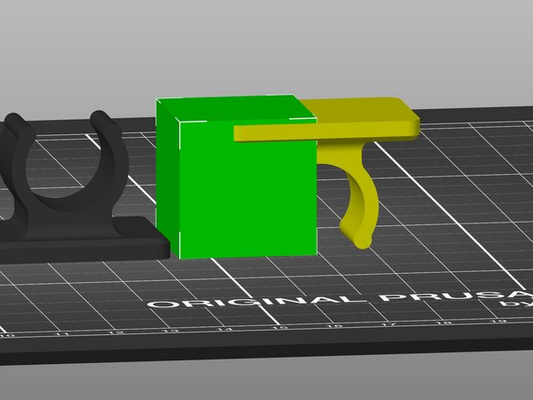
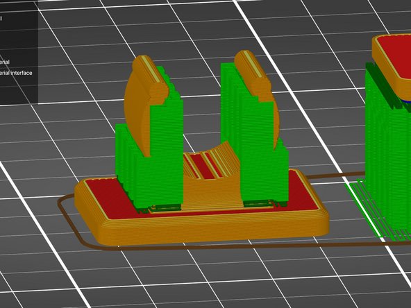
For this example, we have used the same support settings with two different orientations of the same model, to illustrate that proper orientation can make a significant difference in printability.
-
To change between the 3D and preview views, use the icons at the bottom left of the visualization window, or select Window > 3D/Preview.
-
-
-
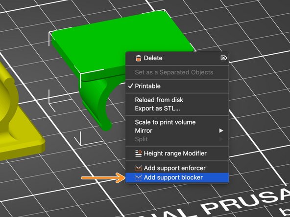
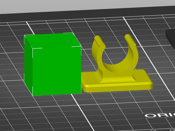
You can selectively add support to only certain areas of your model using support enforcers and blockers. For this example we will add an enforcer to the model on the left and a support blocker to the model on the right.
-
Right click on the model you wish to add a support blocker to, and select Add support blocker. Follow the same instructions for a support enforcer, but select Add support enforcer.
-
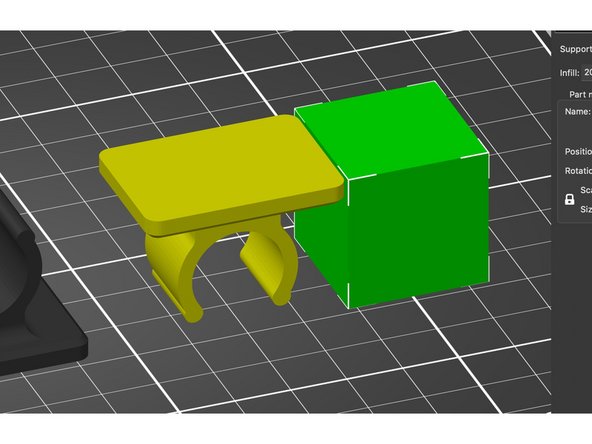
A 1"x1" cube, sphere, cylinder or slab will be generated based on your selection. The dimensions of this object can be modified by selecting it and using the scale tool from the lefthand tool bar, by selecting and dragging the square handles for each axis.
-
-
-
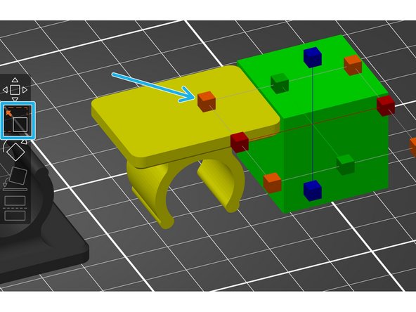
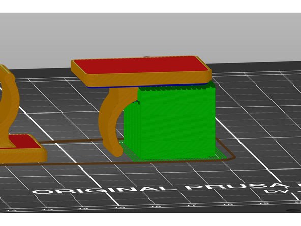
In order for a support blocker to work, it must reach from the floor of the build plate all the way to the surface you wish to block supports from.
-
In order for Slic3r to obey a support blocker or enforcer, you must select For support enforcers only in the Supports dropdown menu before processing and previewing (slicing) the print.
-
Position the support blocker by dragging it to the desired location, and select Slice now to preview the model with blocked supports.
-
-
-
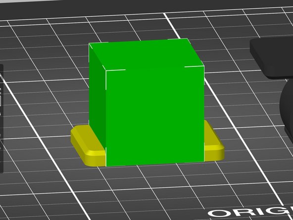
This same process can be used for support enforcers to apply supports where they otherwise would not have been automatically generated by Slic3r, for example.
-
Drag the support enforcer to the desired location, and select Slice now for a preview of how it will print.
-
-
-
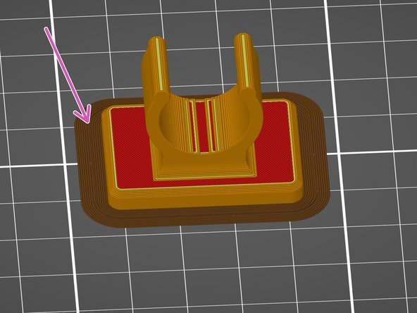
Adhesion between the print and bed is important, and most often where prints begin to fail. In order to create some extra adhesive property to your print, select the Brim checkbox before slicing your model. This will add a radiating single layer 'skin' several mm out from the edge of your part and increase its surface area.
-
-
-
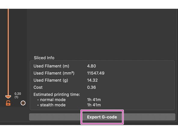
In order to be readable by the printer, the file you have just prepared must be exported as G-code and loaded onto the printer's memory card.
-
After you have selected the Slice now button at bottom right of the screen, the same button now reads Export G-code.
-
Remove the SD card from the printer and insert it in an SD reader. If there is not one on your computer, you can disconnect and use the USB SD card reader attached to the computer in the general assembly area at the IDC.
-
Select the Export G-code button in Slic3r and then select the SD card to export it to. A name will automatically be generated based on the original file name but you can change it as you wish.
-
-
-
Before printing, ensure your build plate is free of dust and oil by spraying once with Isopropyl alcohol and wiping with a paper towel. the bottle of alcohol can be found on the wooden shelving unit containing the Prusa printers in the IDC general assembly area.
-
Also, visually inspect the roll of filament currently loaded in the printer to make sure there is a reasonable amount of filament left on the roll, and inspect the path it follows to the printer's extruder to ensure its end is loaded into the machine.
-
If you need to change the roll of filament for any reason, to change the desired color or replace a spent roll, refer to the document How to unload and reload filament from the Prusa MK3 dry box for instructions.
-
-
-
With the SD card re-inserted in the printer, push the knob on the face of the printer's display like a button to enter the main menu.
-
Turn the knob clockwise to scroll down to Print from SD, and push the button again to select it. The printer will begin preheating, and once it has reached the appropriate temperature it will begin printing.
-
Do not walk away from the printer after starting the print. Most failures happen in the first layer, so stick around to make sure the first layer has adhered to the bed properly and things look good.
-
-
-
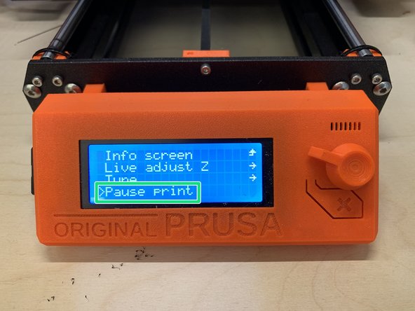
To pause a print due to failure or other issue, press the knob on the front of the display and scroll down to Pause print by turning the knob. Press the knob again to select pause.
-
The printer will stop printing and move the extruder away from the print area.
-
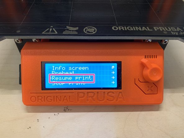
To restart the print from being paused, press the knob on the display face and scroll down to Resume print. Press the knob again to select it.
-
To stop a print, press the knob/button on the face of the display, and scroll down to Stop print. Push the knob again to select it.
-
Stopping a print will effectively cancel all printing, and you will have to restart the print from the beginning to run it again.
-
-
-
When your print has completed, remove the steel sheet from the bed by placing a finger underneath the two front corners of the sheet and pulling upward. It is magnetically held in place and will release with some flex.
-
Flex the bed to detach the print (not too much!). If your part is very small and will not release by flexing the sheet, try to use a fingernail or something made of soft plastic to pick it off.
-
Do not use metal objects or scrapers to remove parts from the steel sheet. The bed surface is soft and can easily be scratched or deformed. Flatness is important to successful printing.
-
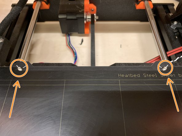
Replace the sheet on the bed by sliding the notched back edge of the steel sheet onto the two M3 screws protruding from the back edge of the print bed, and then place the rest of the sheet down onto the magnetic bed surface.
-
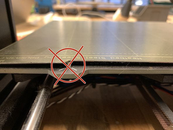
Make sure you do not accidentally leave the sheet resting on top of the screws and that it is completely flat on the bed.
-