Introduction
There are three main steps in using the Fablight FL4500 for cutting sheet: exporting a readable file from your preferred CAD software, processing the file for the Fablight laser using the FabCreator software, and setting up and cutting with the Fablight FL4500. Refer to the following steps in this guide for instruction on how to follow this process.== == Heading text == ==
-
-
In order to process your part file for laser cutting, it must first be exported in .dxf format from you preferred CAD program. This is the only format which can be processed by the Fablight processing software (FabCreator).
-
If you have created a sheet metal component in Solidworks with bend locations in it, refer to the following step for instruction on how to include engraved bend lines on your cut part.
-
-
-
If you have created a sheet metal component file in Solidworks, you can include bend lines in your .dxf which will be engraved for reference in your cut metal part by selecting the option in the .dxf export menu.
-
-
-
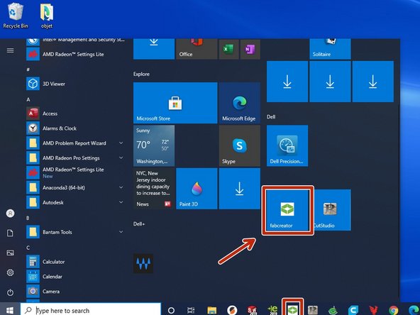
Open the FabCreator software from the start menu or Windows toolbar
-
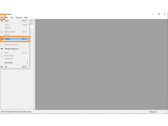
from the top toolbar in FabCreator, select File>Import, and select your .dxf file and Import.
-
Select the correct units based on which units you used to design your part.
-
-
-
Before proceeding to the next step it is important to understand the three different processes performed by the Fablight metal cutting laser:
-
Cut: this pierces and cuts entirely through the sheet in the profile specified by your part geometry using a single width laser beam, so that it is fully released from the sheet.
-
Engrave: this marks the surface using a single width laser beam as a thin outline of whatever specified geometry is assigned to be engraved.
-
Raster: this uses a high resolution back and forth motion (similar to an inkjet printer) to mark a solid, filled in area of the surface.
-
-
-
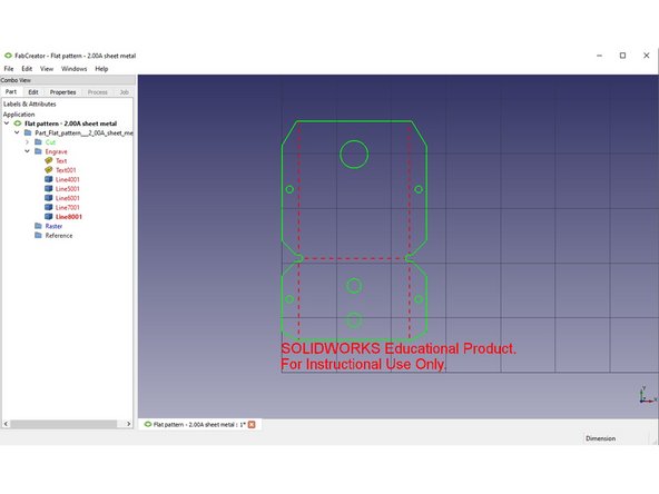
Upon import, FabCreator will automatically assign processes (Cut, Engrave, Raster) by default to your part geometry.
-
In the left panel of the screen, there are categories for each process (Cut, Raster, Engrave), which can be expanded to show which elements of your part geometry have automatically been assigned to those processes.
-
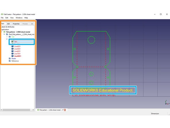
You can select from the list of entities in the process folders and the correspondent part geometry will be highlighted yellow on screen. You can also directly select geometry on the screen by clicking on it.
-
If something has been assigned a process by default which is undesirable, you can select the entity from the expanded category at left of the screen and drag it into the desired process category, i.e. move an entity from Engrave to Cut, etc.
-
When you have imported your file, it may have unwanted text or geometry included from whatever CAD software it was exported from. Follow the steps above to select it, and then use the Delete key on the keyboard to remove it.
-
Any geometry shown on screen will be processed according to its assigned color/process. If you don't want it to be performed in one of those processes by the laser, delete it or click and drag it to the Reference category in the left panel of the screen.
-
-
-
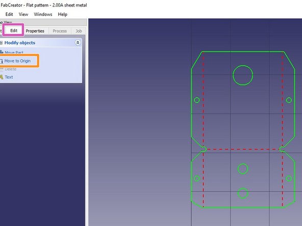
If you have removed text or geometry from your part layout, it is possible the part's location will need to be adjusted so that it sits at the origin of the workspace (X0,Y0). See below:
-
The bottom left corner of the workspace grid where your part geometry is shown represents the point the machine will recognize as the origin point of your part. If your part is not at X0, Y0 in the grid, it will be treated exactly the same way by the laser cutter and could produce unexpected results.
-
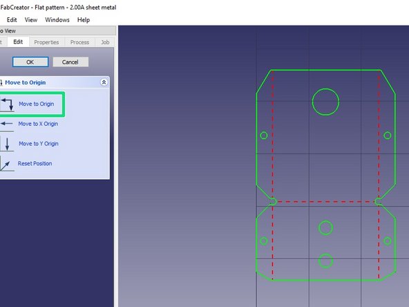
Select the Edit tab in the left panel of the screen
-
From that menu, select Move to origin
-
The submenu will allow you to choose different commands for moving your part to origin X, Y or both. You will want your part geometry at both X and Y zero.
-
-
-
It is vitally important to choose the correct material factors when processing your file. This includes type of material and thickness. Failure to do this properly can result in damage to the machine.
-
Select the Properties tab in the left panel of the screen.
-
Expand the Type category menu and select SHEET.
-
Expand the Material category menu and select the material you are using.
-
Expand the Material Type category menu and select TYPICAL.
-
Generally, all other information fields can be left as defaults.
-
Expand the Thickness category menu and select the thickness of the material you will be cutting.
-
Select the green Accept button at bottom of the left panel of the screen after you have double checked your selections.
-
-
-
Failure to add tabs for retention can result in damage to your part or the machine. This is an important step which must not be overlooked.
-
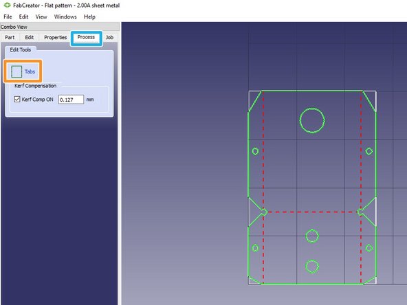
Select the Process tab in the left pane of FabCreator, here you will create tabs which will keep your part delicately attached to the sheet you cut from to prevent it from falling out or moving .while cutting.
-
Select Tabs.
-
Kerf Compensation (displayed under the tabs button) should be selected (checked) by default. If for some reason it isn't, select the check box to activate it.
-
Once you have entered the Tabs workspace, simply click directly on the lines of geometry wherever you want tabs to be. The tabs will be represented by small magenta squares on screen after placement.
-
It is recommended you use at least three tabs on any outside profile, to establish adequate points for keeping the part attached to the sheet without pivoting during cutting.
-
Generally, default tab length values do not need to be altered, this default works well across many materials and thicknesses.
-
-
-
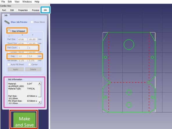
Select the Job tab in the left pane of FabCreator. This is where you will finalize and save your process, thickness and material selections in a format which will then be transferred to the Fablight metal laser.
-
If you wish to cut more than one of the same part, select the Step and Repeat check box, and enter number of instances in the X and Y direction, as well as spacing between each part.
-
Confirm your process and material selections are as intended in the indicated area of the window. This should include the material you are cutting, the thickness, and outside dimensions.
-
Insert a USB drive into your computer.
-
After you have double checked everything, select the green Make and Save button at the bottom of the window, and save your file to the USB drive, which will be inserted in the Fablight laser machine.
-
-
-
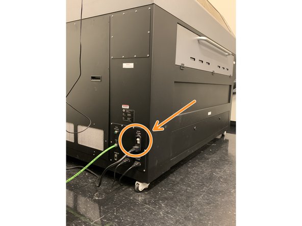
On the lower left side of the machine you will find the power switch. Activate it to power on the machine.
-
The machine will take a few moments to fully power on, and will be ready for initialization when the home screen shows on the main display.
-
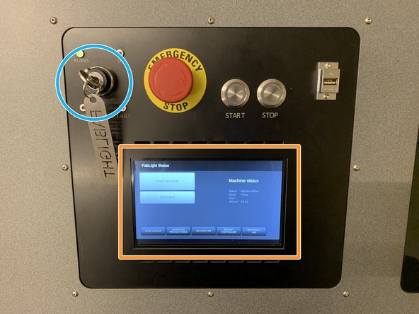
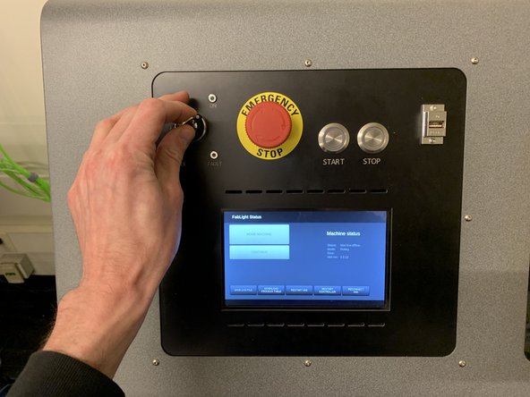
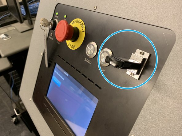
Insert the key, and turn it to the right until it stops. It will spring back to the insertion position after turning. The interior lights of the machine will power on and the machine will begin to initialize.
-
-
-
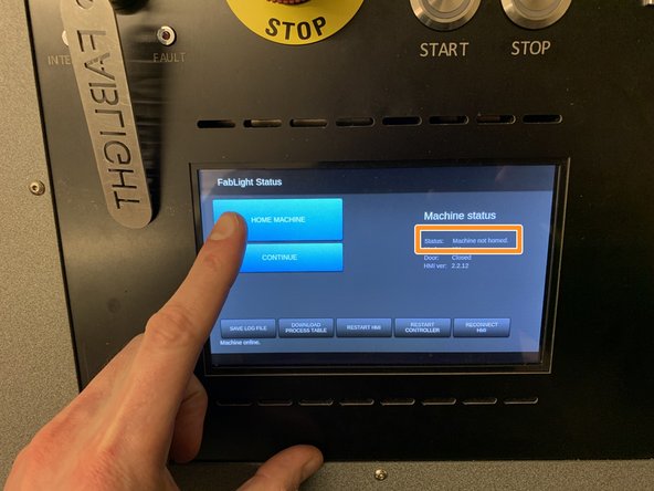
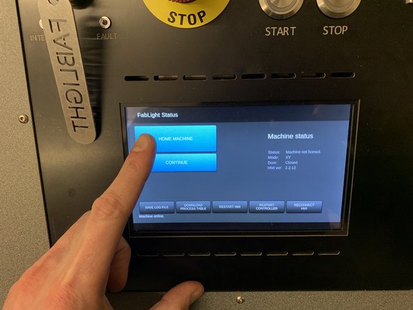
The machine will take up to a minute to initialize, and the main option buttons on the touch screen display will turn from grey to blue.
-
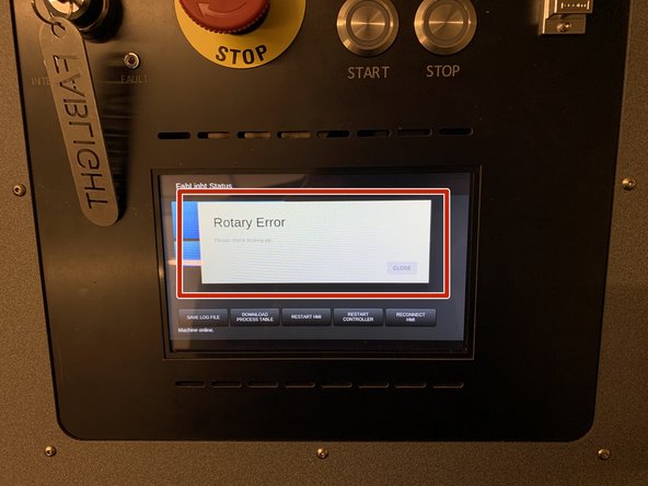
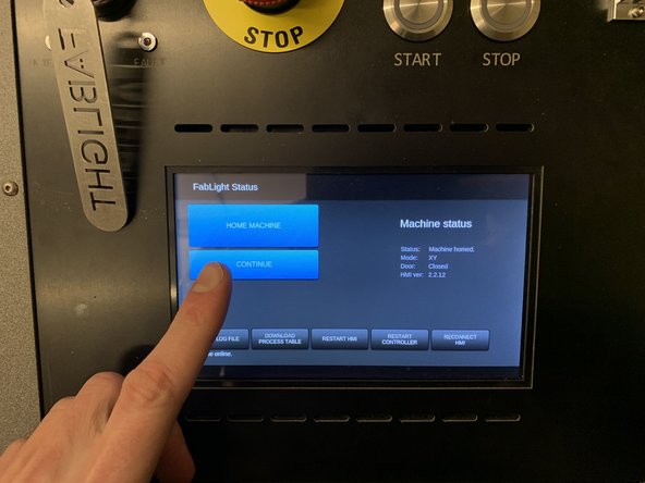
On the touch screen display, press the Home Machine button. The homing process will take a few moments, after which the screen will display Machine Homed in the Machine Status portion of the home screen.
-
Did you get a Rotary Error message when homing the machine? If so, proceed to steps 12 and 13. If not, proceed to step 14.
-
-
-
If you received a Rotary Error while homing the machine, you will have to release the locking pin on the T (4th) axis inside of the machine.
-
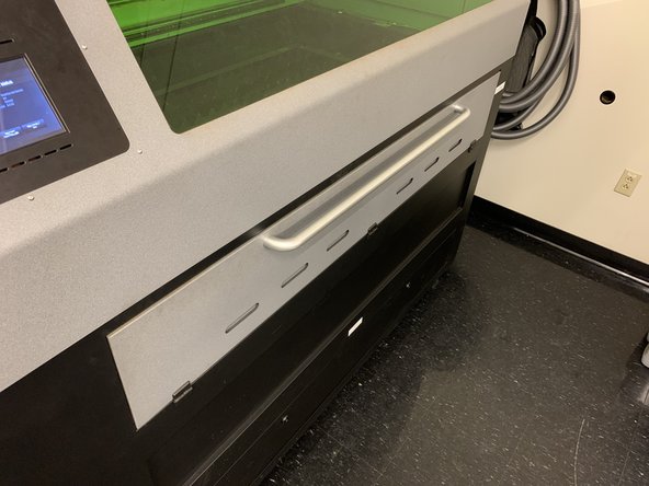
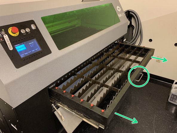
Grab the handle of the front door of the machine and gently pull it open. It will fold downward.
-
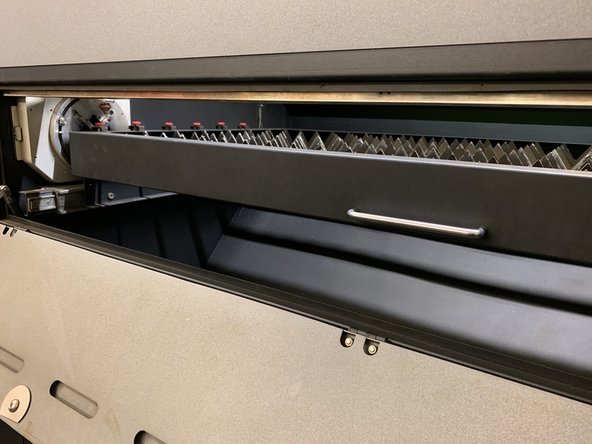
Once opened, grasp the handle of the work table and push it back into them machine until it clicks into its second position.
-
-
-
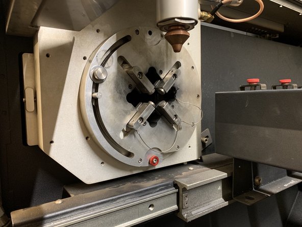
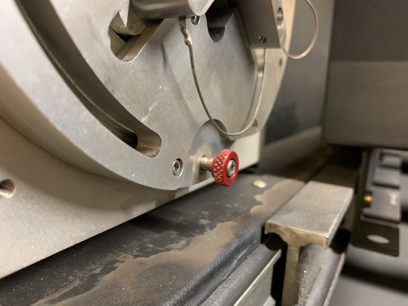
After moving the table to its second position, look to the round work holding chuck to your left.
-
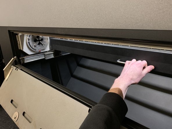
At the bottom of the chuck, there is a small pin with a red, knurled handle. Pull the pin out until it stops. This releases the rotary axis and allows the machine to home itself completely.
-
Pull the table back to its original position until it clicks into place, and close the front cover.
-
Return to the touch screen, and again press Home Machine. The homing process will successfully commence.
-
-
-
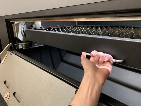
Open the front door of the machine once more, and pull the handle on the front of the work table until the table rolls out of the machine.
-
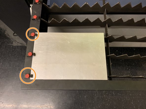
Lay your sheet on the work table surface, and slide one edge underneath the thumbscrew clamps lining the left edge of the work table.
-
Tighten at least two points of clamping along the edge of your sheet to secure it.
-
Once your workpiece is secure, push the table back into its first locking position until it clicks into place.
-
Close the front door of the machine.
-
The work table MUST be in its first locking position (closest to you, and covering the rotary axis chuck) in order to cut sheet. If it is in its second locking position, the machine will be in rotary mode, and will not cut your sheet.
-
-
-
Insert a USB drive into the available slot on the main control panel.
-
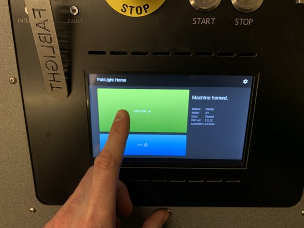
On the touch screen display, select Continue.
-
Select New Job.
-
-
-
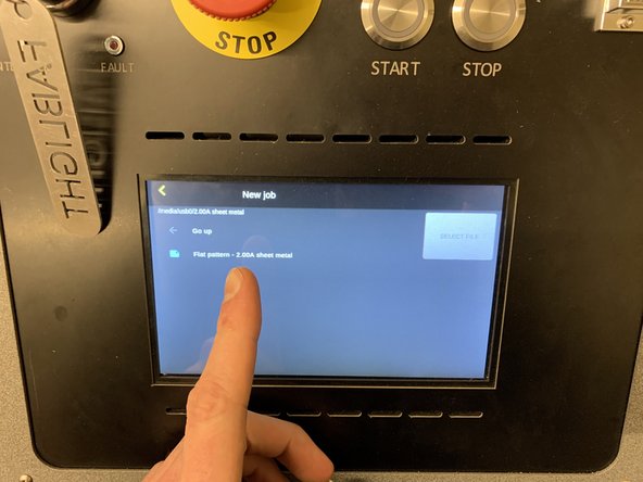
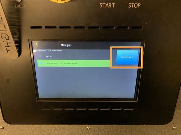
Whatever files and folder are on the USB drive will be displayed. Select the .FAB file you saved in FabCreator.
-
Select Load File.
-
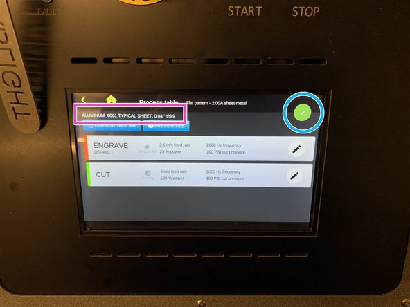
The following screen will display information on laser power, speed and frequency, etc. for each process, as well as information about material and thickness. Verify the material and thickness are accurate for the material you will be cutting.
-
Once you have verified the material and thickness information is correct, select the green check mark in the top right of the screen to proceed.
-
-
-
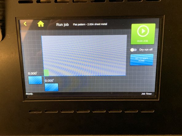
The screen will display a virtual layout of the work table, with a green rectangle representing the dimensions of the file you have selected to be cut.
-
Look into the machine through the main window and observe the location of the red laser dot. The position of the dot represents the bottom left origin of your cut file, as represented on the screen.
-
If necessary, the cutting area can be repositioned on the sheet by dragging the blue flags on the display in X or Y.
-
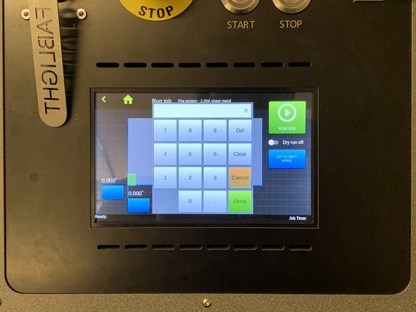
Tip: if you are unable to achieve the positional accuracy required by dragging manually, double tap the blue flag in the axis you wish to reposition.
-
A numeric display will pop up, which will allow you to enter an absolute coordinate in the machine work area to place your work. Absolute coordinates are in relation to the machine zero point, all the way at bottom left of the work table.
-
-
-
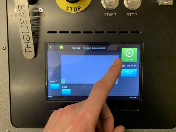
Once you are certain your position is correct, the next step is to cut the part.
-
In the top right corner of the display screen, press the RUN JOB button.
-
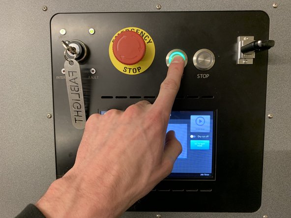
After pressing the RUN JOB button, the START button above the touch screen will begin to blink green. Press this button to begin the cutting process.
-
Once activated, the machine will automatically activate a dust collection system which produces one loud, constant noise like a vacuum cleaner, and a second, intermittent thumping noise. This is all normal behavior for the machine. Refer to video in next step for example.
-
-
-
The video displays what proper cutting action should look like. Visible sparks should take place on the bottom of the sheet.
-
If you are experiencing a lot of sparking on top of the sheet you are cutting, press the STOP button above the touch screen display immediately. The machine's optics can suffer damage with prolonged top surface sparking.
-
If you experience any issues, find a shop staff member immediately to deal with the problem. If none are available, stop using them machine and contact them through email to let them know of the issue immediately.
-