Introduction
The Universal Laser Systems 9.150 is a 120 Watt laser cutting machine with a working area of 24" x 36" (600mm x 900mm). See the bottom of this guide for a list of acceptable and unacceptable materials to cut with this machine, and a troubleshooting guide.
-
-
The basic functions of a laser cutter are as follows:
-
Cutting burns all the way through the media you are working on, so that after this process you can fully remove the separate piece from the larger board.
-
Single line engraving uses the same single fine line as cutting does, but only marks the surface and does not cut all the way through.
-
Raster engraving uses a rapid side to side motion while the laser is activated to mark an area surface of the media without going all the way through.
-
-
-
The software platforms you will use for design and preparation in this lab are Rhino and CorelDraw. These are both loaded onto the lab computers which are connected to the laser cutters.
-
Files for laser cutting can be created in softwares such as Rhino 3D, AutoCAD, Adobe Illustrator, Inkscape, Solidworks, Inventor, and Fusion 360, and saved for use as .dxf, .ai, .eps, .svg, .pdf, or .bmp (for raster only) formats. These formats will all open in CorelDraw.
-
For simplicity, this guide will take you through the process using CorelDraw.
-
-
-
Before anything, check these two things when importing a file from outside software:
-
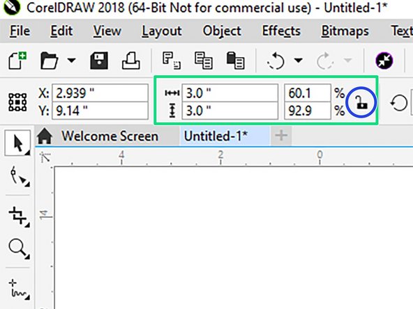
Make sure your geometry is the correct size. In CorelDraw, this can be done by window selecting your artwork and looking in the top left corner at the dimensions in the toolbar.
-
If you need to adjust the overall size of your artwork and want it to remain proportionate, make sure the padlock icon is set to the locked position when entering a value. It can be toggled by clicking the icon.
-
Check to make sure you have no duplicate geometry underneath your intended cut lines. This can be done by selecting any given line and deleting it to see whether there is a duplicate underneath. Edit>Undo to reverse the delete action if there is none.
-
If you have duplicate lines underneath each other, the laser will cut those lines twice, which can be a fire hazard or damaging to the parts you are cutting.
-
-
-
Ensure all lines to be cut (either all the way through or just single line surface marking) are set to Hairline lineweight.
-
Lineweight and color options can be changed using the Object Properties panel on the right side of the screen. If the object properties panel does not appear, go to Window>Dockers>Object Properties to make it appear.
-
Click on the object you wish to change, and select Hairline from the lineweight dropdown menu.
-
The Universal software uses different RGB colors to differentiate between the operations of cutting, engraving and raster. To designate colors to each entity, select and click the color swatch at the right edge of the screen for the desired operation. Left click to change the fill color, right click to change the outline.
-
RGB Red (255,0,0) is used for cutting operations.
-
RGB Blue (0,255,0) is used for engraving operations.
-
RGB Black (0,0,0) is used for raster operations.
-
-
-
The Universal software uses different RGB colors to differentiate between the operations of cutting and engraving. To designate colors to each entity, select and click the color swatch on the right side of the screen for the desired operation. Left click to change the fill color (raster only), right click to change the outline.
-
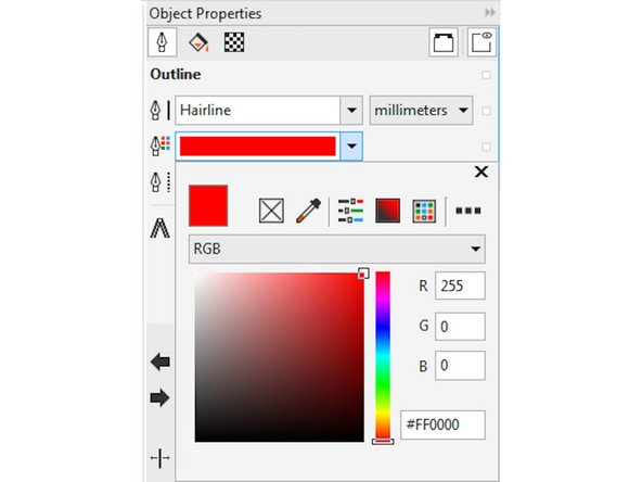
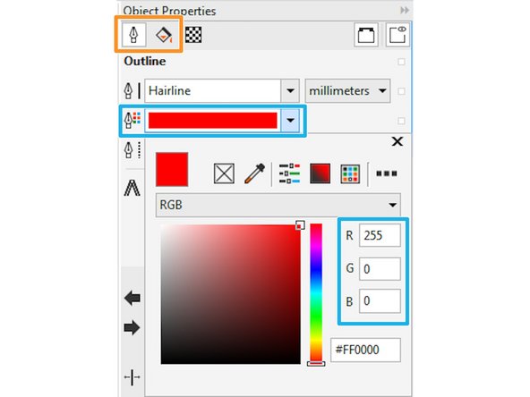
Colors can also be set in the Object Properties by using the color dropdown menu and entering the RGB values manually.
-
Select the paint bucket icon to change fill color (only used for rastering) or the pen nib icon to change the outline color (for cutting operations). Then select the color dropdown menu and enter the value.
-
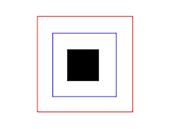
RGB Red (R: 255,G: 0, B: 0) is used for cutting operations which will go all the way through the material.
-
RGB Blue (R: 0, G: 0, B: 255) is used for single strike line operations which do not cut all the way through the material. for instance, fine detail line art.
-
RGB Black (R: 0, G: 0, B: 0) is used for raster operations, which use rapid back and forth motions to cover the surface of an entire area. The fill color of the object must be black in order to achieve the intended result.
-
-
-
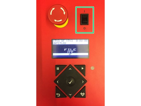
Flip the small, black switch next to the machine main keypad.
-
The machine will go through an initialization procedure in which the cutting head will perform a set of motions before settling.
-
The computer should be logged in before activating the power switch, otherwise the laser cutter can freeze and not establish communication with the computer. If this happens, shut down and start again with logging into the computer first.
-
-
-
After turning on the machine, open the cover and place your media on the bed.
-
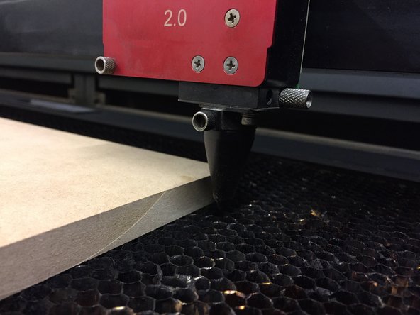
Before moving the cutting head, visually check to make sure the cone will clear your media height to ensure it will not crash.
-
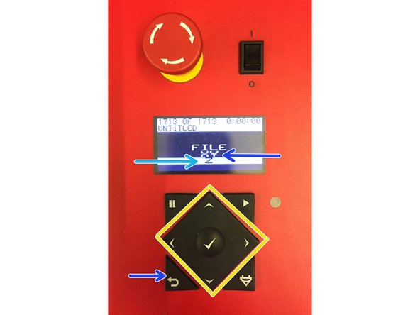
If it will not clear your media, on the machine's main control screen, tab down to 'Z' using the up/down arrows on the machine's keypad, followed by 'OK'
-
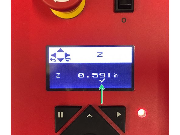
Tab over to the .010 discrimination in the z value shown on the control panel screen using the left/right arrow keys, and press and hold the down arrow to lower the table.
-
After you are certain the cone will clear your media, press the return key to return to the control panel's home screen, and use the up/down arrows to select 'X/Y' from the list, followed by 'OK'
-
Use the arrow keys to move the cutting head over your media by holding them down until it is over the area you intend to cut from
-
-
-
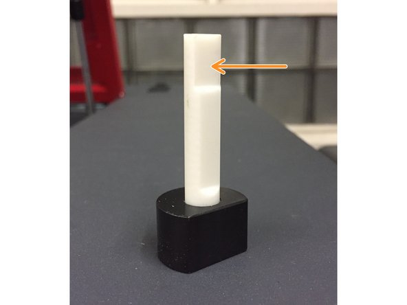
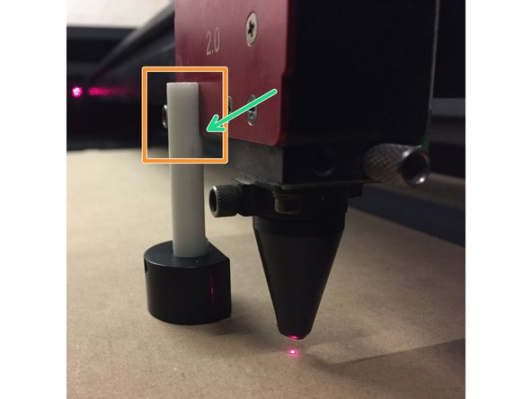
Place the flat face of the focus tool against the face of the carriage.
-
Observe the space between the angled lower edge of the focus tool's face and the bottom of the carriage. If you cannot contact the face of the carriage with the flat face of the focus tool, the table must be lowered more.
-
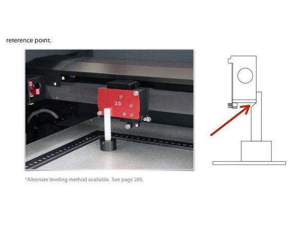
If the bottom of the carriage is not touching the angled intersection of the focus tool, the table must be raised (see last photo for position).
-
Return the the table (Z) height adjustment as done previously.
-
using the up/down arrows, adjust the table height until the top of the focus tool begins to push away from the face of the carriage.
-
Once this happens, lower the table again just to the point that the focus tool returns to its flat position against the face of the carriage. Reposition it again by lightly pushing it against the carriage as done originally and making sure it is in the correct position and wasn't pushed out of place.
-
The laser is now focused. Remove the focus tool and place it back next to the machine control panel
-
-
-
In CorelDraw, Go to File>Print and select ILS9.150D from the list of printers, and then select Preferences
-
Under the Materials Database tab select from the dropdown menus to choose which material you will be cutting. That will establish baseline Power, Speed and Frequency settings for you to begin working from.
-
After selecting a material, enter the material thickness in the dialog box.
-
It is important you make sure to enter a material thickness, this will control how the machine processes power and speed settings which are critical to safety and success.
-
Once you have selected a material and thickness, make sure to hit Apply to confirm your selections
-
-
-
Under the Manual Control tab, make sure all colors you are using have the intended operations assigned to them, i.e. red and blue as 'Vect' (cutting/engraving) and black as 'Rast'(raster engraving).
-
Assigning the 'Vect' or 'Rast' processes is done by choosing one or the other from the dropdown menu at right of the window.
-
Make sure the Z axis is set to OFF, and that 'Both' is selected in the Laser dropdown menu.
-
IMPORTANT: When selecting a color from the left side of the screen, click it once to select and highlight it. When done editing, you must click it once more to deselect it. It is possible to accidentally select multiple colors at once, and settings you change will be applied to all selected colors.
-
When you have checked and designated your settings, hit the big red Set button in the menu window, followed by OK. The settings window will close and return you to the regular Print menu.
-
Hit Print to send the file with settings to the Universal control software, from where you will control the laser cutter.
-
-
-
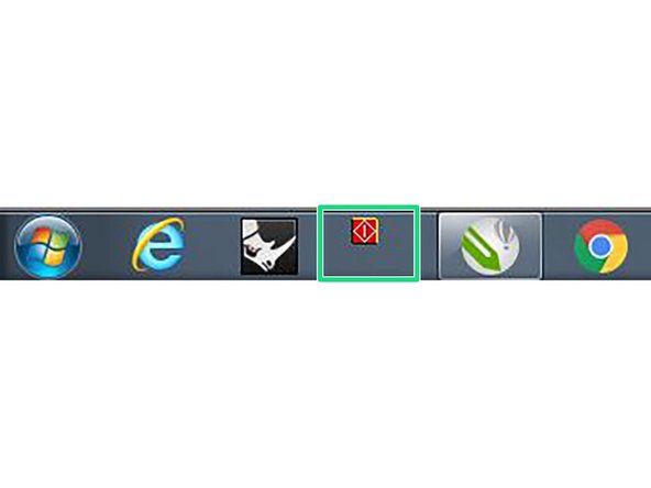
The control software should automatically open upon hitting Print, if it does not open as the front window, click on the icon in the Windows toolbar.
-
Your sent file should be displayed in the main window of the control software. In order to move the file to the intended location of your media, do one of the following:
-
Using the Move tool, select and drag to a location in the machine's work area. The rulers in the software's work area match the rulers on the machine's table.
-
Using the Focus View tool, click at a specific location in the work area. The cutting head will move to that point on the table.
-
Now select the file with the Move tool again and highlight which corner you want snapped to the cutting head's current location and select To Pointer. The artwork should snap to the pointer on screen.
-
-
-
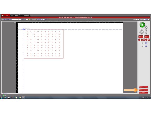
Before cutting, verify the settings you programmed were translated to the control software by selecting Settings. This will open the same menu you originally created your settings in and allow you to observe whether they are as intended.
-
Close the laser cutter cover (gently).
-
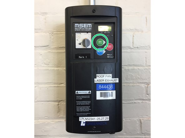
Move to the wall and activate the exhaust system by pressing the green ON button.
-
DO NOT BEGIN CUTTING WITHOUT THE EXHAUST RUNNING, THIS IS EXTREMELY IMPORTANT.
-
-
-
When you have finished setting your focus, verifying your settings and turning on the exhaust system and are ready to cut, press the large green Play button in the control software. This will begin the cutting.
-
Do not walk away from, or turn your back on the laser cutter while it is operating. Fires can occur quickly and catastrophically.
-
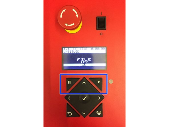
Cutting can be paused by selecting the Pause button in the Control software window, or the hard Pause key on the machine control panel directly. To restart after pausing, hit the Play button again.
-
When cutting has finished, wait a few seconds for remaining smoke to clear and then open the cover to remove your part(s).
-
Before moving anything, check to make sure the cutting went all the way through your material by holding the cut part down and trying to lightly pick up the corner of the media. It should be separated. If you move your media in any way side to side it will be impossible to realign and you will have to cut again with fresh material.
-
-
-
If your part did not cut all the way through, you will need to either decrease speed or increase power to achieve the intended result. This is done in the control software by selecting Settings in the main window, clicking on the Materials tab and dragging either the Power slider higher or Speed slider lower.
-
It is recommended this adjustment be made in no more than increments of roughly 10% at a time, and that you adjust only one setting (power OR speed) at a time. Increasing/decreasing by more than that can result in excess burning or even fire.
-
If you did raster and/or engraving on your part(s) and the end result is either too dark or too light, enter the Settings panel and Select the Materials tab again to make adjustments by dragging the Power slider in the positive or negative direction, depending on the desired result.
-
Raster or engravings that are too light can sometimes just be run again at the same power settings used before, on the same part, because the raster will be performed over itself again. Increasing or decreasing settings is typically used when beginning a new cutting session.
-
Refer to the next step to learn how to re-run cutting of only selected or desired processes and shutting off others which do not need to be re-run.
-
-
-
If you want to selectively re-run one or more processes (for instance, if your part has cut through but your raster is too light), enter the Settings menu and select the Manual tab.
-
Click on the process(es) you wish to turn off, and on the right side of the window select Skip from the dropdown menu. Do this for each process you wish to ignore. Click on the Set button, and then OK.
-
In the main window, click the green Play button to run the program again.
-
-
-
If you notice your cutting line is very broad and emits excess smoke while cutting, it is likely caused by one of the following problems:
-
The laser is out of focus. Re-check the focus of the laser as described in steps 4 and 5 and try again.
-
If focusing the laser again does not solve the issue, it is likely the optics are dirty. In this case, shut down the machine, leave a note indicating the issue on the machine and notify staff immediately (email addresses are listed on the whiteboard in the assembly area).
-
IN CASE OF FIRE: small amounts of flame are typical during cutting, they usually stay close to the cutting beam or just trailing it. if flames get worse than this do the following:
-
Press the Pause key on the machine keypad or in the control software and open the lid of the machine. Use the oven mitt next to the machine to pat the location of the fire.
-
If the fire cannot be controlled using the oven mitt, use the small fire extinguisher can next to the machine and spray it directly onto the fire until extinguished.
-
-
-
If you have sent a file to the Universal control software from CorelDraw or Rhino and part of the artwork is not showing up in the work area window:
-
Check your lineweight selections again to make sure they are set to hairline for cutting and engraving.
-
Check your color selections again to make sure they are the correct RGB values, and that you have the correct colors corresponding to those selections set in the Manual Settings of the Universal laser print preferences.
-